|
|

|
You will need
the circuit board and all the electronics including the BASIC STAMP
1 chip set; these are located in one of the pink poly bags. The
other pink poly bag contains the sensor board and it's components,
which are assembled separately, so to make life easier, don't mix
the two.
Be sure to work in a ventilated,
well lit area, with tile or thin carpeting on the floor; thick carpets
like to eat little dropped parts!
|
|

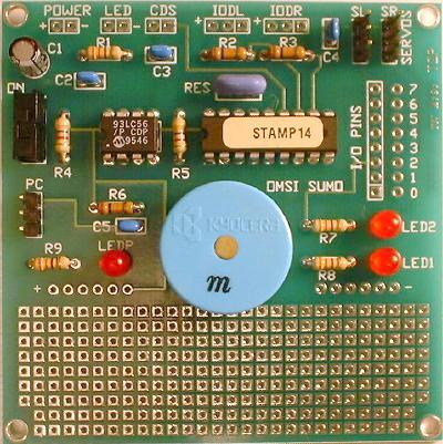
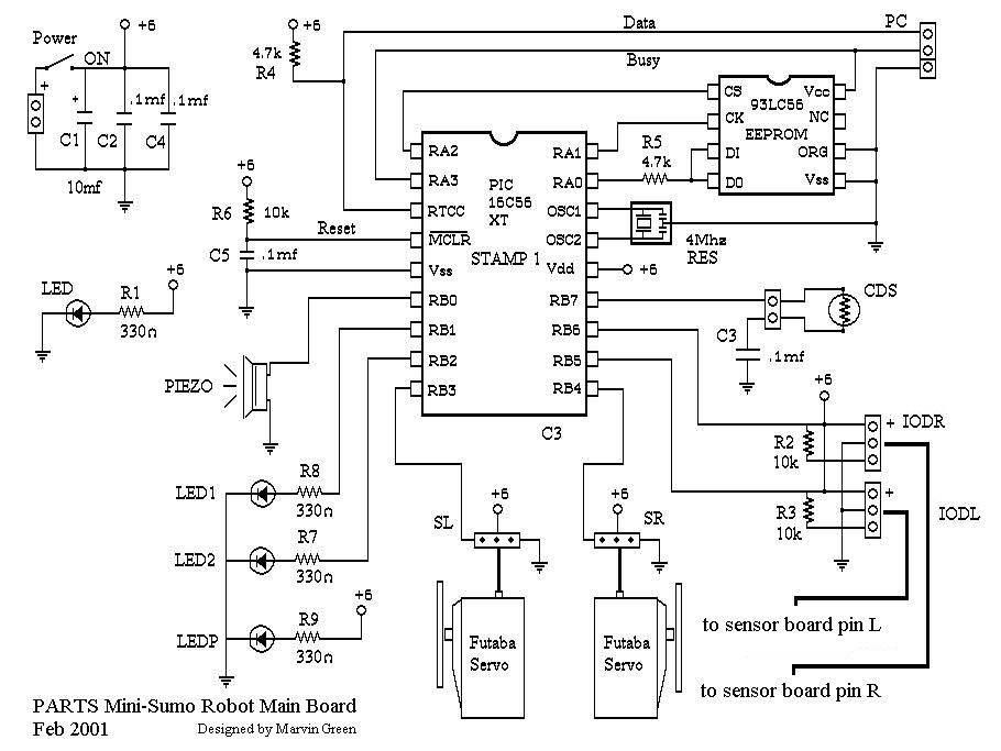
View Board Layout
|
Solder
on the smallest electronic components first. Identify the resistors
by it's color code and solder them to their location.
R2, R3, R6 - 10k resistors - brown black orange (R2 and R3 are optional
if you use the sensor board included with the Mark II kit, but are
mandatory if you use Sharp GP2D15 sensors)
R1, R7, R8, R9 - 330 ohm - orange orange brown (these are always
used)
R4, R5 - 4.7k - yellow, purple, red (these are also always used)
|
|

View Populated Board
|
Next
solder on capacitors C2, C3, C4, C5, these capacitors are marked
with the number 104.
Solder
in the BASIC STAMP 1 IC chip and the EEPROM chip paying close attention
to the orientation of the notch in the IC.
The
resonator RES can now be soldered in place. This provides the 4
MHz clock for the BASIC STAMP.
|
|

|
The
LED's can be soldered in place now. The LED's are polarized, and will
only work if soldered in the correct orientation. Make sure the cathode
(negative) side of the LED faces the right hand side of the circuit
board. The silk screen image of the LED shows the cathode as the flat
side id the image. |
|
|
Solder
in capacitor C1 and orient the negative and positive pins correctly,
the positive pin is marked on the circuit board.
The three 3 pin headers can be soldered into positions SL, SR and
PC connector locations. The pins shipped with the Mark II kits stick
out too long under the circuit board once they are soldered in.
You should clip them off on the underside of the board, being careful
to aim them away from yourself and others, as they will shoot off
rapidly when clipped.
The ON/OFF switch can now be soldered to the circuit board, followed
by the piezo speaker. Note: some of the piezo's leads don't quite
fit in the holes provided on the circuit board. You might have to
ream the holes out a bit (but not too much) to make them fit.
|
|

